Digital Auxiliary Gauges for the Pontiac Fiero
Introduction
Goal: Use an Arduino to read the current oil pressure and battery voltage and display it on two 3-digit 7-segment LED displays.
For the final project of a digital electronics class offered through the UFV physics department, I chose to take what I had learned and apply it to the creation of digital versions of two auxiliary gauges in the centre console of my car. I chose to do this with the Arduino platform, which was not taught in class, but I found it easy to pick up based on the topics I had learned.
The project went through several revisions. The version I completed for the class consisted of two separate display PCBs with 7-segment displays -- one for each digital gauge -- with the rest of the the electronics being an Arduino Uno and a breadboard with some voltage dividers. The "final" version (if I don't revisit the project later) had all of the electronics on one PCB, abandoning the Arduino hardware for a standalone ATmega 328 microcontroller. This final version also included provisions for a 16x2 character OLED display. The reason for this is because I was interested in the MPGuino at the time and wanted to see if I could integrate it into my gauges.
I encountered a few specific challenges when coming up with my design. The first being how to read in the analog signals that the stock gauges used. The next major problem was how to interface with the LED displays given the lack of pins on a ATMega328 microcontroller. I explored the use of shift registers, but in the end I found it easier to give each display its own ATTiny 4313 microcontroller, which was programed with code that would receive commands and values over I2C and then set the appropriate pins high or low to drive the display. Not only did this solve the lack of pins issue, but it freed up the main microcontroller from having the handling the display-related processing.
Inputs and Outputs
Oil Pressure
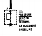
Based on the service manual, the Fiero's oil pressure sender gives a variable resistance to ground, where 90 ohms corresponds to the maximum value on the gauge (80 PSI/550 kPa). It isn't explicitly stated in the manual, but from experiementation I found that a 0 ohm signal (short to ground) corresponds to 0 PSI on the gauge.
One way that the Arduino can read this resistance value is by creating a voltage divider and reading in the value as an analog voltage with one of its analog input pins. Using 5V as the input voltage, 330 ohms as the first resistor in the divider, and the 0-90 ohm sender as the second resistor gives 0 volts when the gauge is at 0 PSI, and 1.071 volts at 80 PSI.
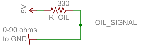
The Arduino's ADCs are 10 bits, meaning that if the ADC input voltage is equal to the voltage powering the Arduino (usually 5V), you get an integer value of 1023. Therefore, you can tell whether you've reached full-scale on the gauge if the value you get is greater than 219. Assuming the sender gives a linear response, it's trivial to figure out the rest of the scale -- an integer value of 110 would be 1/2, 55 would be 1/4, and so on.
Battery Voltage
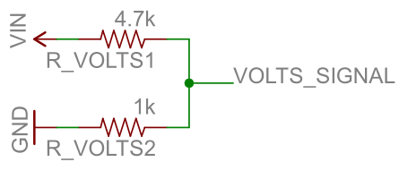
The Arduino's ADC only accepts up to about 5 volts. The car's battery voltage is at about 14 volts when being charged by the alternator, and the stock analog gauge goes all the way up to 18 volts and as low as 8 volts. The solution, once again, is to use a voltage divider so that the a ratio of the voltage is read by one of the Arduino's analog pins. Using resistor values of 4.7k and 1k, gives 3.16 volts out with an 18 volt input and 1.40 volts out with 8 volts in.
The Arduino's Input Voltage
The Arduino's ADC makes comparison's to the Vin supply voltage. Usually this is 5 volts, and if it were exactly 5 volts, then you could take an analogRead() result of 1023 to be 5 volts. However, this is rarely the case. Therefore, if you want to know the absolute voltage of an analog input, you must first determine what the Vin voltage is.
Fortunately, this is already a problem for which a solution exists and is easy to implement because it's just code that you can include into your Arduino sketch. The project is called Secret Voltmeter.
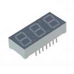
LED Displays
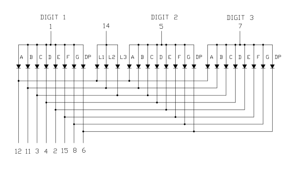
I wanted to create a digital display which looked like something that may have come from the factory. This meant using a 7-segment LED display, which happens to be quite appropriate for the automotive environment with its wide operating temperature. The exact display I ended up using is the LTC-4624JR, which is a multiplexed 3 digit 7-segment LED display. The multiplexed digits means that each digit is turned on individually for a moment with the correct segments enabled before being switched off again and the next digit being lit up. This works due to persistence of vision, but if you were to record a video of the display you would see it flickering. This also means that the Arduino ends up spending a lot of its time just keeping the displays working as normal. The bottleneck of the Arduino's digitalWrite() functions became quite apparent, and so I ended using direct port manipulation which let me toggle the segments significantly quicker. I also decided to learn about I2C and give each display its own microcontroller -- an ATtiny 4313. This meant that the main microcontroller was free to do more computation.
Physical Design
This is an early version with the displays being separate.
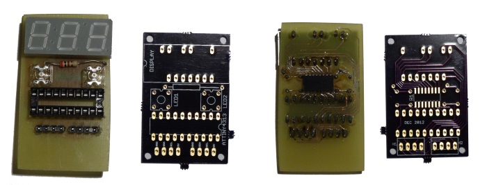
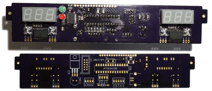
This is the "final" version, with a single PCB from OSH Park. It mounts into the same frame that the original analog gauges used, which locates it in the auxiliary cluster.